70cm 6-Element Yagi - 432 MHz
6-element Yagi for 432 MHz. 6 mm aluminium rod, 894 mm boom. Simulated in 4NEC2 at 1.5 m height, 11 segments per element.
Performance Data
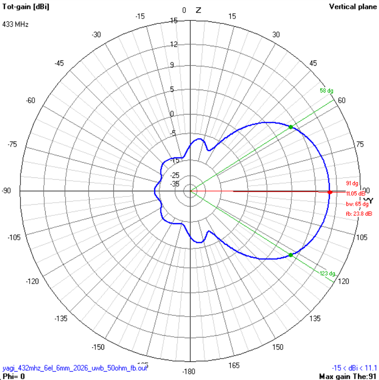
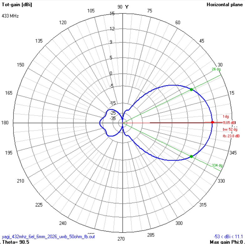
| Gain | 11.05 dBi |
| F/B | 23.8 dB |
| -3 dB E-plane | 65° |
| -3 dB H-plane | 52° |
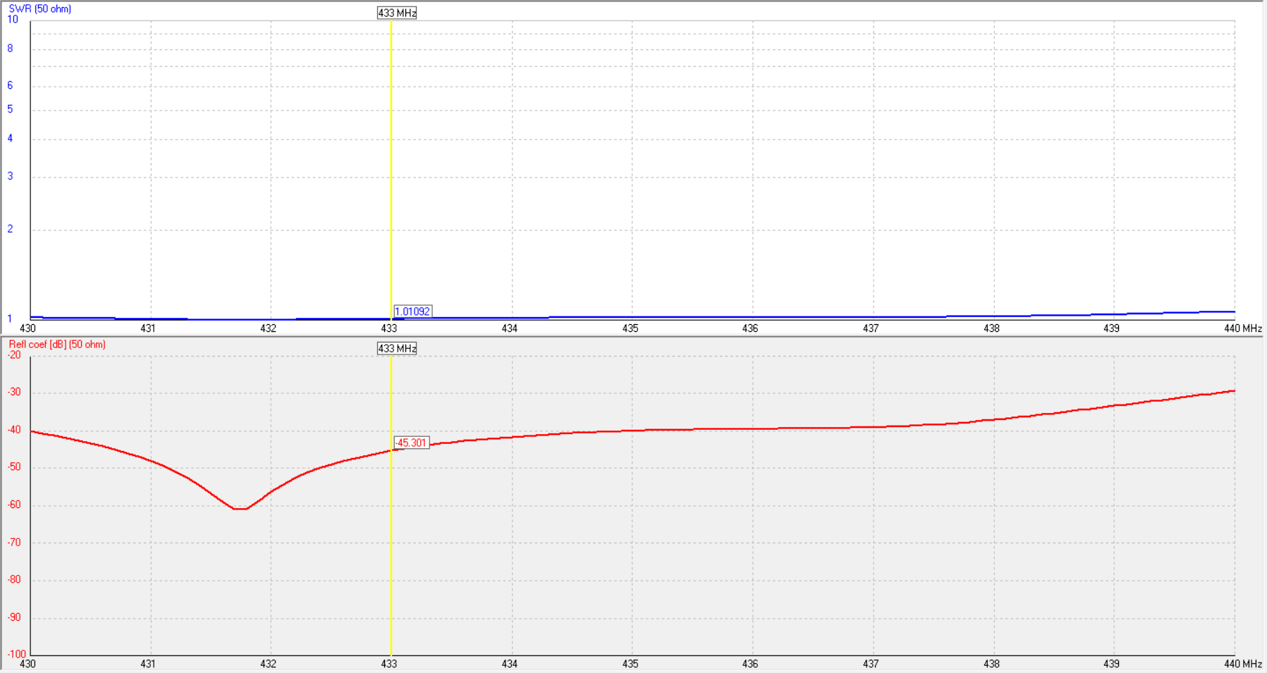
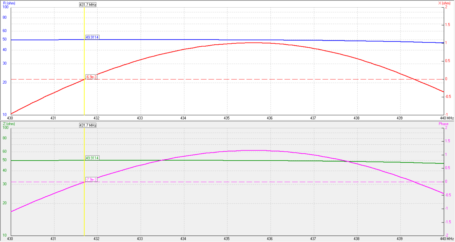
| Impedance | 50 Ω (direct feed) |
| Polarisation | Horizontal |
| Boom length | 894 mm |
| Electrical length | 1.29 λ |
| Weight | < 500 g |
Geometry
Ø 6 mm elements - insulated from boom. All positions from reflector end.
| Element | Position (mm) | Length - 6 mm (mm) |
|---|---|---|
| Reflector | 0 | 336 |
| Driven | 155 | 331 |
| Director 1 | 221 | 302 |
| Director 2 | 396 | 288 |
| Director 3 | 626 | 272 |
| Director 4 | 894 | 244 |
More diameter columns will be added as they are simulated. Do not use these lengths with a different rod diameter without re-simulating.
Pattern & SWR Plots
Build Notes
Feed: Direct 50 Ω. Split driven element at centre with ~5 mm gap. Centre pin to one half, shield to the other. No matching network needed.
Boom: Non-conductive (fibreglass, PVC, wood) = simplest. Metal boom = insulate elements with nylon/HDPE clamps. Through-boom on metal = re-simulate with boom correction.
Precision: 1 mm ≈ 1.5 MHz at 432 MHz. Use a calliper.
Cable: RG-58 loses ~0.25 dB/m at 432 MHz. Keep runs short or use RG-213 / LMR-400.
Polarisation: Horizontal as built. Rotate boom 90° for vertical (FM).
Materials
| Item | Qty | Specification |
|---|---|---|
| Aluminium rod (6 mm) | ~2 m total | 6061-T6 or similar |
| Boom | ~1 m | 15-20 mm square or round (aluminium, fibreglass, PVC) |
| Insulated clamps | 6 | Nylon or HDPE, sized for 6 mm rod |
| SO-239 or N-type connector | 1 | Panel mount, 50 Ω |
| Coaxial cable | 5-10 m | RG-213 or LMR-400 recommended (50 Ω) |
| Stainless steel hardware | 1 set | M3/M4 screws, nuts, washers |