2m / 70cm Multiband Yagi - 145 / 435 MHz
Interleaved 2m (4-element) and 70cm (3-element) Yagi on a single ~978 mm boom. Single feed point on the 2m driven element. 8 mm parasitic elements, 6 mm driven element. Simulated in 4NEC2 at 1.5 m height, 11 segments per element.
Performance - 2m (145 MHz)
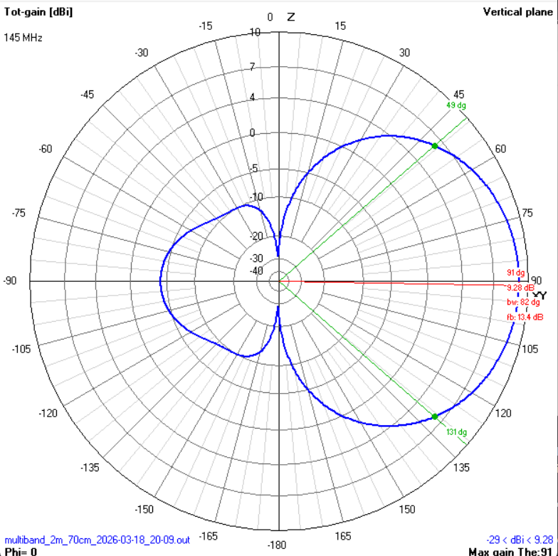
| Gain | 9.28 dBi |
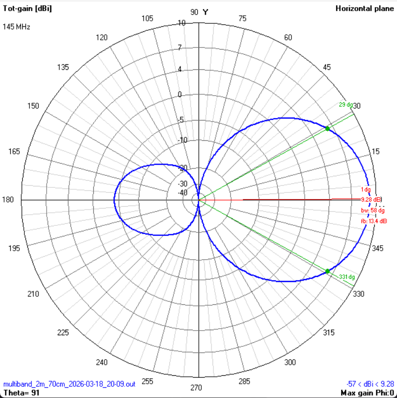
| F/B | 13.4 dB |
| -3 dB E-plane (vertical) | 82° |
| -3 dB H-plane (horizontal) | 58° |
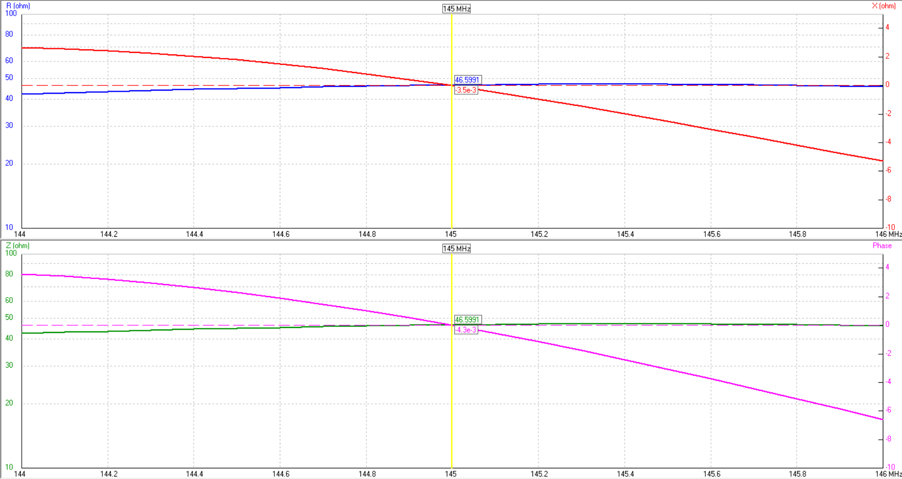
| Impedance at 145 MHz | 46.6 − j0.0 Ω |
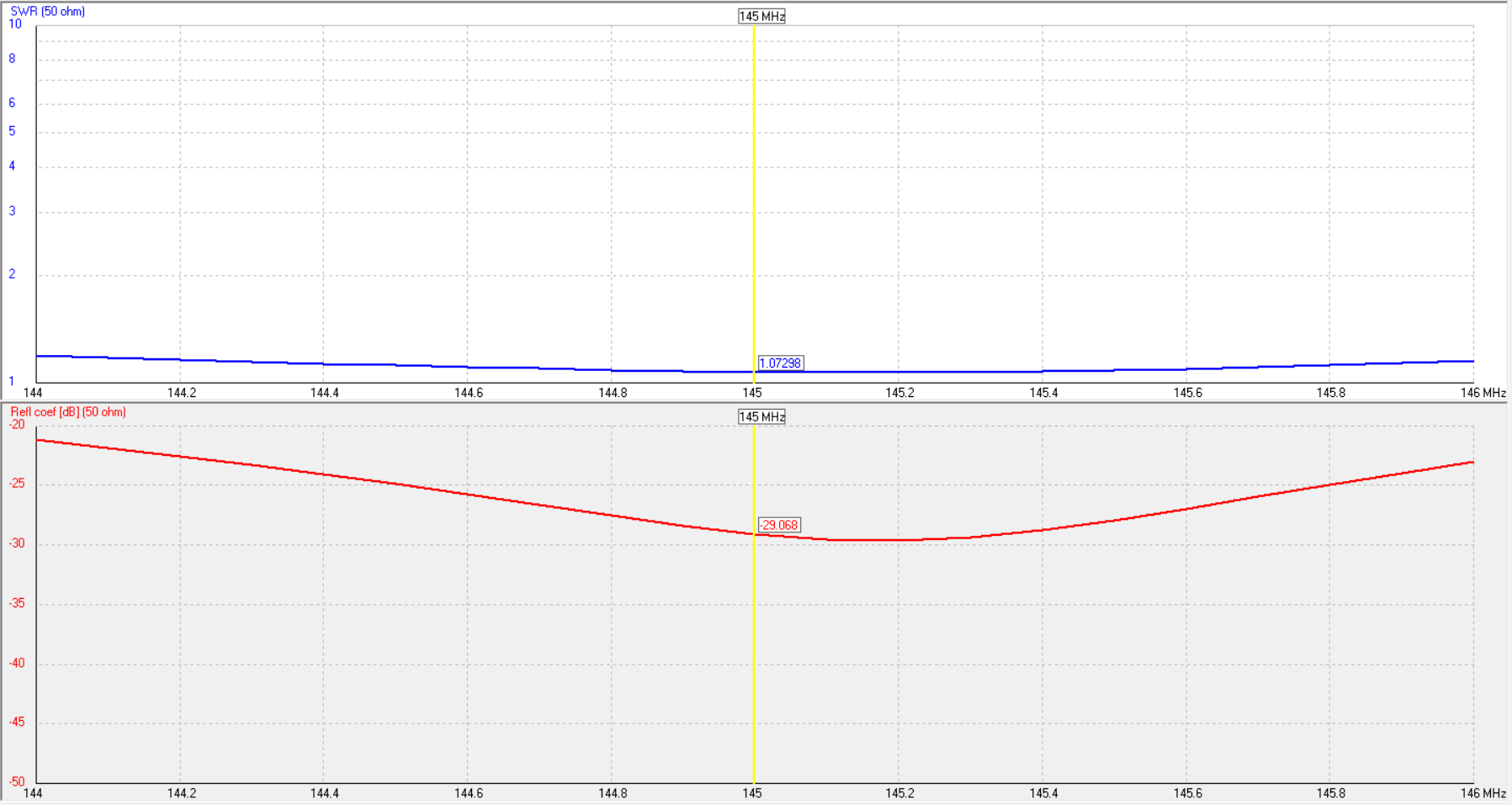
| SWR min | 1.07:1 @ 145 MHz |
| SWR bandwidth (< 1.5:1) | > 144-146 MHz (full band) |
| Refl. coeff. | −30.0 dB @ 145 MHz |
| Polarisation | Horizontal |
Performance - 70cm (435 MHz)
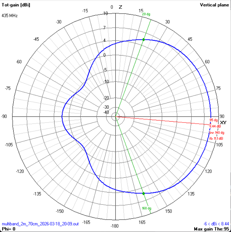
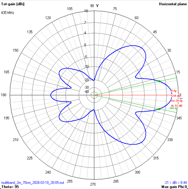
| Gain | 8.44 dBi |
| F/B | 11.1 dB |
| -3 dB E-plane (vertical) | 140° |
| -3 dB H-plane (horizontal) | 24° |
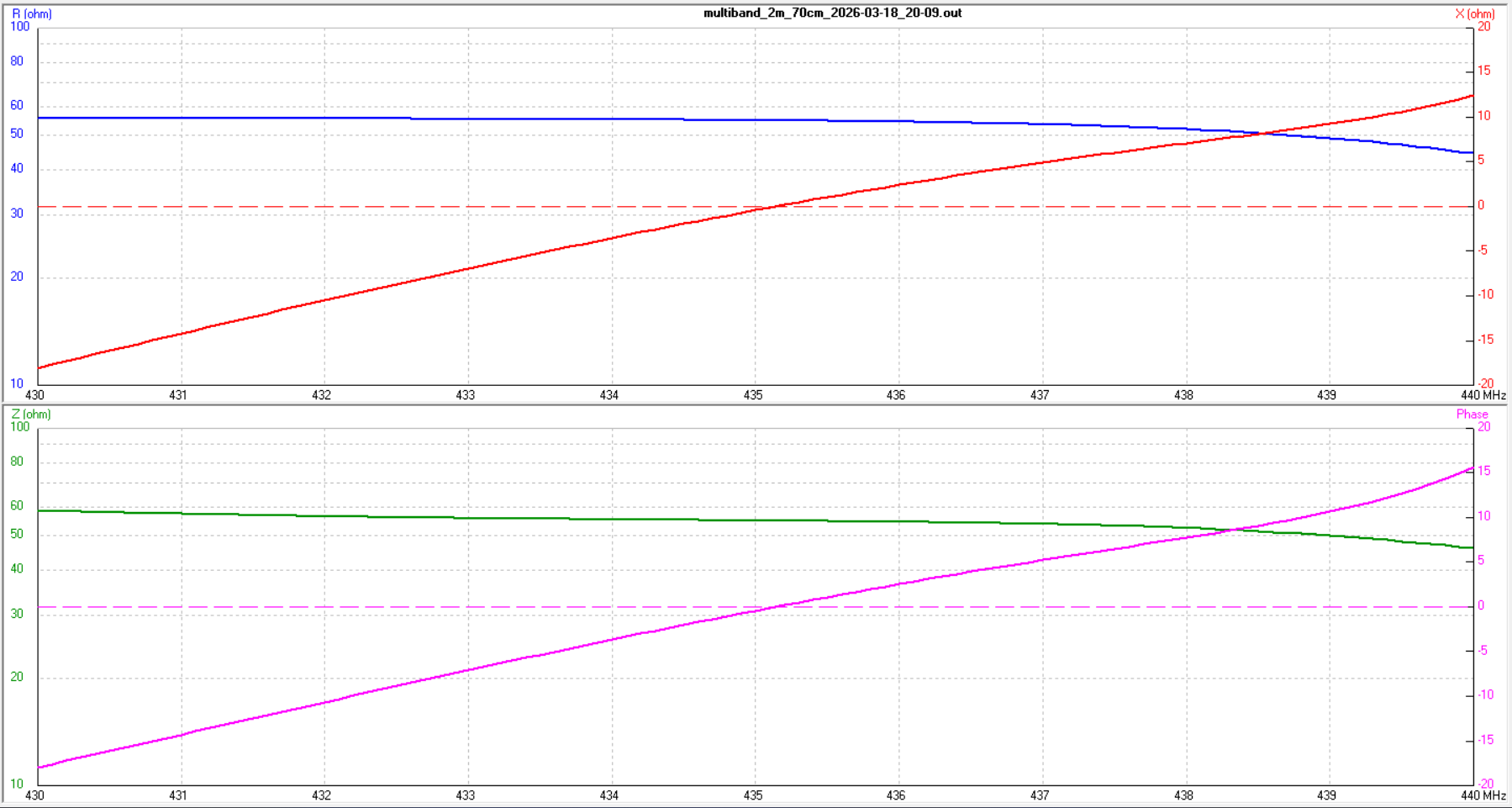
| Impedance at 435 MHz | ~57 + j0 Ω |
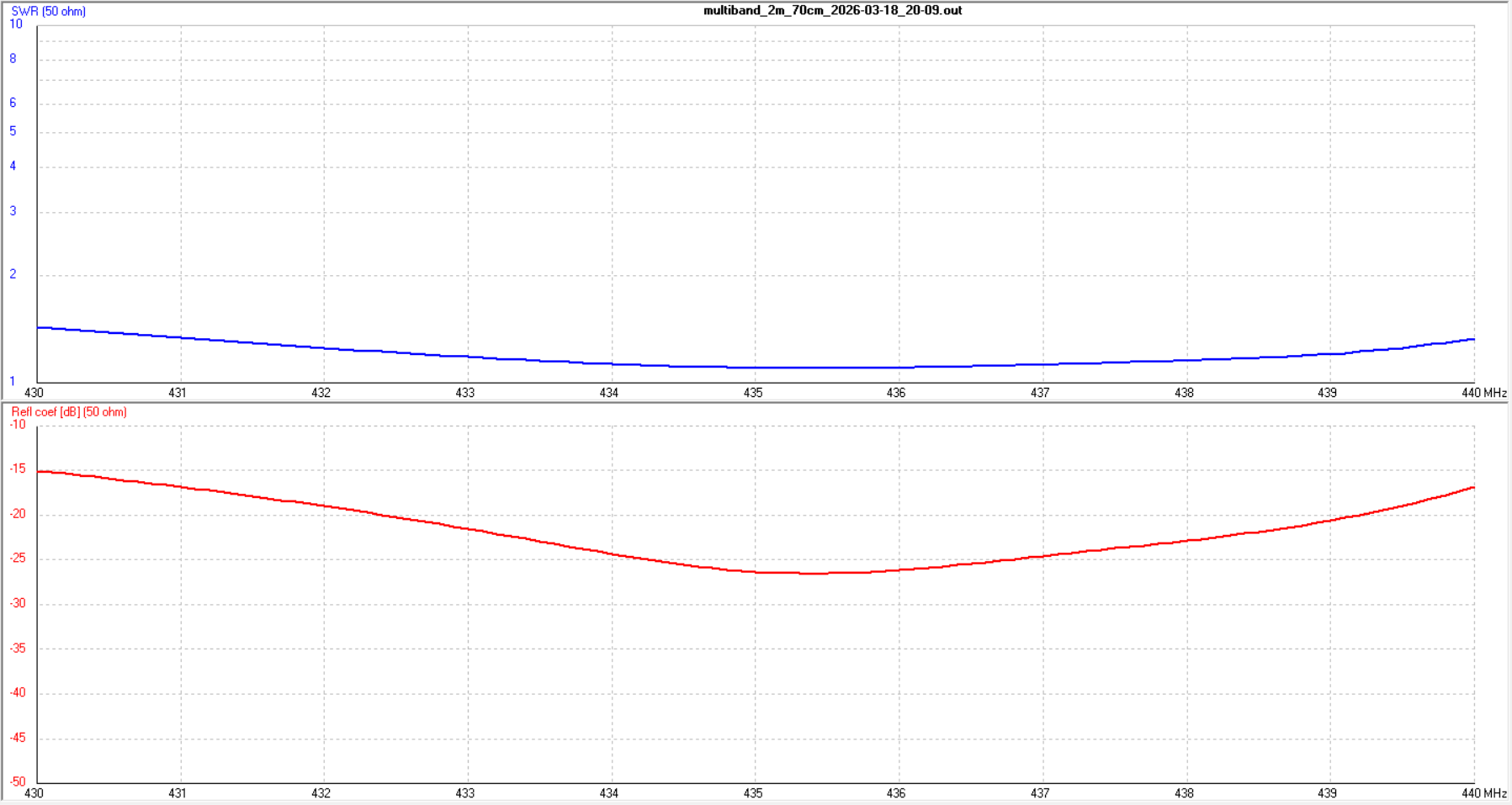
| SWR min | ~1.1:1 @ 435 MHz |
| SWR bandwidth (< 1.5:1) | 430-440 MHz (full band) |
| Refl. coeff. | ~−27 dB @ 435 MHz |
| Polarisation | Horizontal |
Geometry
Single feed on the 2m driven element (6 mm Ø). All parasitic elements 8 mm Ø. Insulated from boom. Positions from boom start.
| Element | Position (mm) | Length (mm) | Ø (mm) | Band |
|---|---|---|---|---|
| 2m Reflector | 34.9 | 1031.7 | 8 mm | 2m |
| 2m Driven | 260.0 | 987.0 | 6 mm | 2m |
| 70cm Reflector | 304.8 | 310.9 | 8 mm | 70cm |
| 70cm Driven | 449.5 | 305.7 | 8 mm | 70cm |
| 2m Director 1 | 485.2 | 925.9 | 8 mm | 2m |
| 70cm Director | 719.2 | 272.1 | 8 mm | 70cm |
| 2m Director 2 | 977.3 | 893.0 | 8 mm | 2m |
Total boom length: 977.3 mm (from first to last element). Do not change element lengths without re-simulating.
Plots - 2m (145 MHz)
Plots - 70cm (435 MHz)
Build Notes
Feed: Single feed on the 2m driven element (6 mm). Split at centre with ~5 mm gap. Centre pin to one half, shield to the other. Direct 50 Ω - no matching network.
70cm coupling: The 70cm elements are all parasitic. They couple through the 2m driven element which acts as a ~3λ/2 element at 435 MHz. No separate feed for 70cm.
Boom: Non-conductive (fibreglass, PVC) is simplest. Metal boom = insulate all elements. Through-boom on metal = re-simulate with boom correction.
Precision: Element spacing is critical for multiband operation. At 435 MHz, 1 mm ≈ 1.5 MHz shift. Measure carefully.
Cable: RG-213 or LMR-400. Cable loss matters on 70cm - keep runs short.
Polarisation: Horizontal as built. Rotate boom 90° for vertical (FM).
Materials
| Item | Qty | Specification |
|---|---|---|
| Aluminium rod (8 mm) | ~4.5 m total | 6061-T6 or similar - parasitic elements |
| Aluminium rod (6 mm) | ~1 m | 6061-T6 - 2m driven element |
| Boom | ~1050 mm | 15-20 mm square or round (aluminium, fibreglass, PVC) |
| Insulated clamps | 7 | Nylon or HDPE, sized for 8 mm / 6 mm rod |
| SO-239 or N-type connector | 1 | Panel mount, 50 Ω |
| Coaxial cable | 5-10 m | RG-213 or LMR-400 recommended (50 Ω) |
| Stainless steel hardware | 1 set | M3/M4 screws, nuts, washers |