2m / 70cm Cross Yagi - LEO Satellite Wideband
Cross-polarised 2m/70cm Yagi with two separate feed points (not multiband). 2 elements on 2m (vertical), 5 elements on 70cm (horizontal), 640 mm boom. Designed for hand-held LEO satellite tracking and portable use. Wideband: full 144-146 and 430-440 MHz coverage. Two variants: 5 mm and 4 mm parasitic elements. Simulated in 4NEC2 at 1.5 m over real ground.
Two Variants
Both variants share identical element lengths and positions. Only the parasitic rod diameter differs:
5 mm variant: Parasitic elements 5 mm Ø, driven 6 mm Ø. No mounting hardware modelled.
4 mm variant: Parasitic elements 4 mm Ø, driven 6 mm Ø. Includes modelled mounting screws (3 mm Ø, 15 mm) near the driven elements - more realistic for through-boom builds.
Performance - 2m (145 MHz)
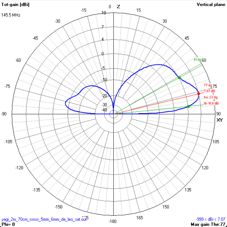
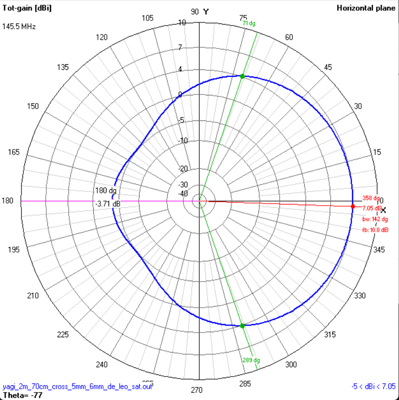
| Gain | 7.07 dBi |
| F/B | 10.8 dB |
| -3 dB E-plane (vertical) | 23° |
| -3 dB H-plane (horizontal) | 142° |
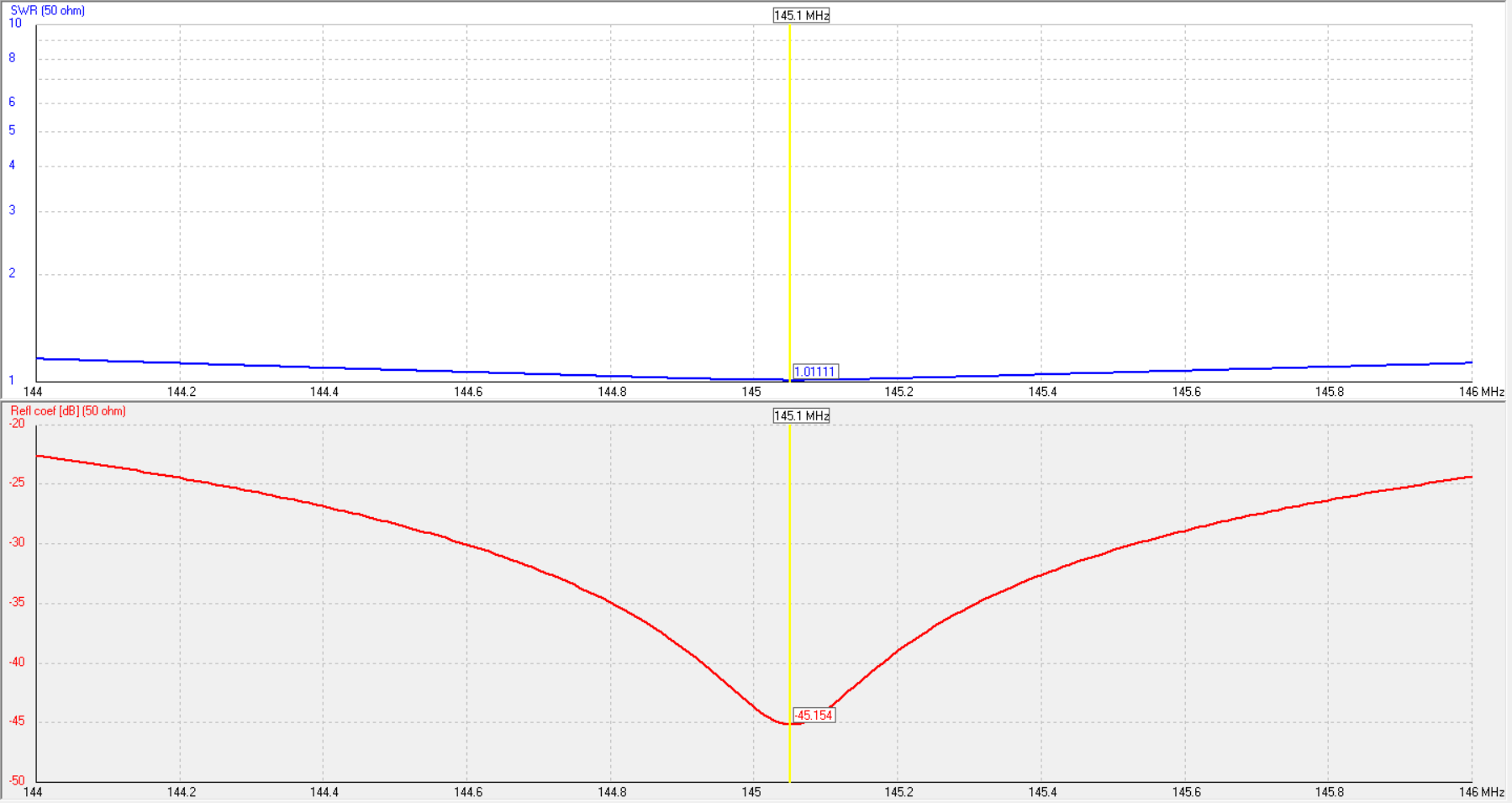
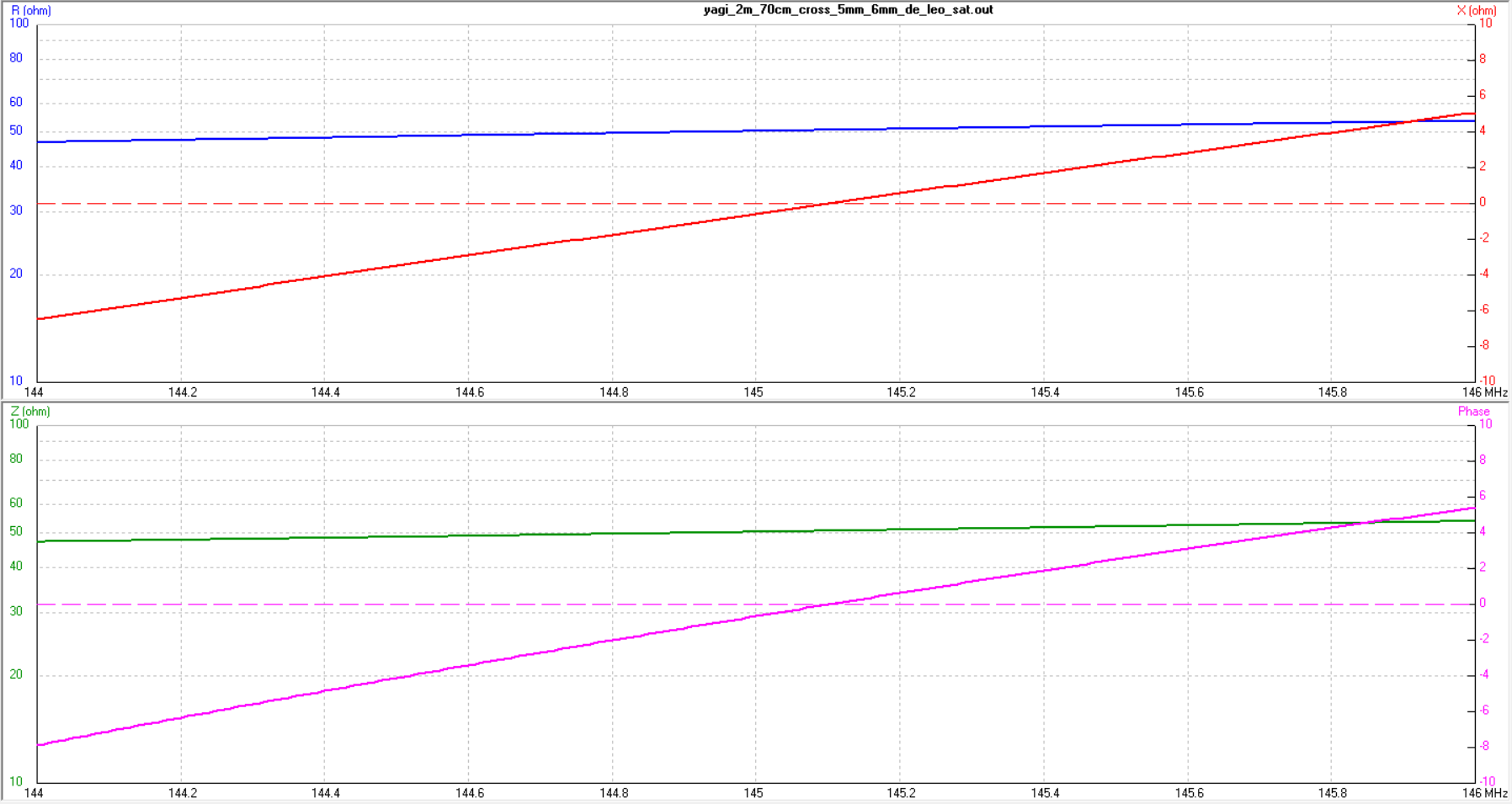
| Impedance at 145 MHz | ~50 + j0 Ω |
| SWR min | 1.01:1 @ 145 MHz |
| SWR bandwidth (< 1.2:1) | > 144-146 MHz (full band) |
| Polarisation | Vertical |
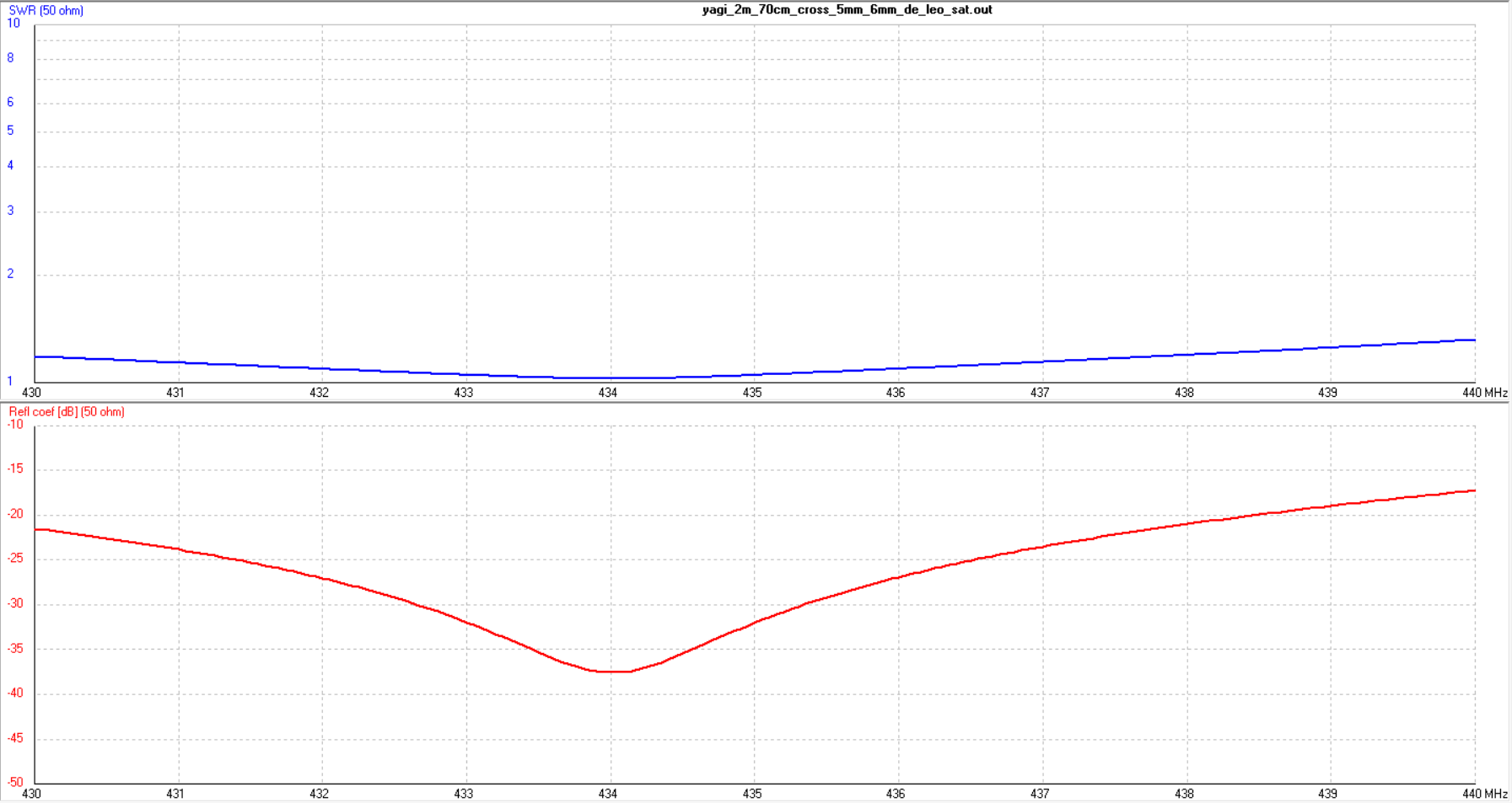
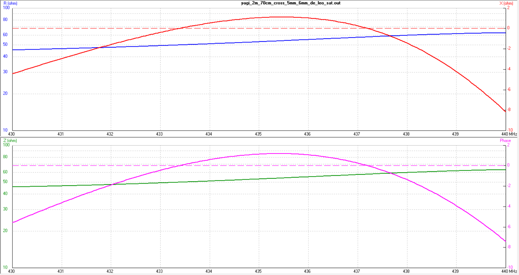
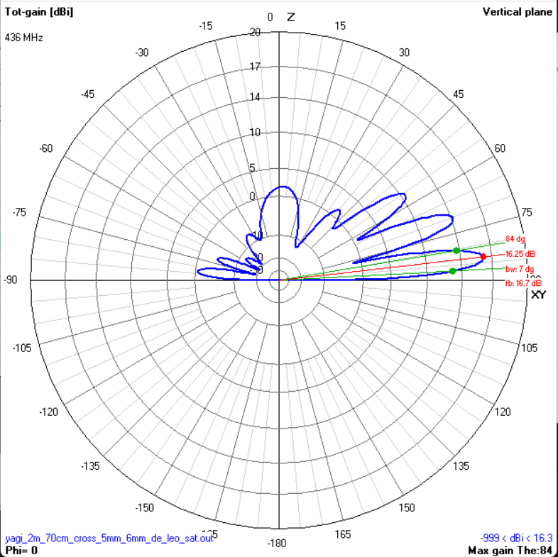
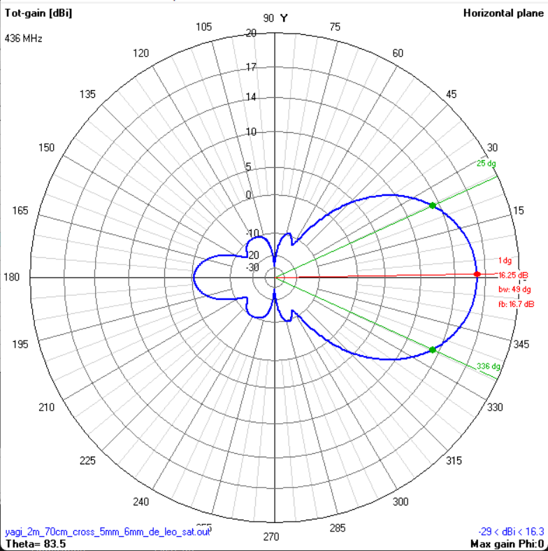
Performance - 70cm (436 MHz)
| Gain | 16.25 dBi (includes ground gain at 1.5 m) |
| F/B | 16.7 dB |
| -3 dB E-plane (vertical) | 7° |
| -3 dB H-plane (horizontal) | 49° |
| Impedance at 434 MHz | ~50 + j0 Ω |
| SWR min | ~1.05:1 @ 434 MHz |
| SWR bandwidth (< 1.3:1) | 430-440 MHz (full band) |
| Polarisation | Horizontal |
Geometry
Cross configuration: 2m elements run vertical, 70cm elements run horizontal, both on the same boom. Two separate feed points. Positions measured from boom start (2m reflector at 0 mm). Element lengths are identical for both variants - only the parasitic rod diameter differs. Do not change lengths if you switch diameter without re-simulating.
2m Band - Vertical (2 elements)
| Element | Position (mm) | Total length (mm) | Ø parasitic (mm) 5/4 | Ø driven (mm) 5/4 |
|---|---|---|---|---|
| 2m Reflector | 0 | 1033 | 5 / 4 | - |
| 2m Driven | 365 | 937 | - | 6 / 6 |
70cm Band - Horizontal (5 elements)
| Element | Position (mm) | Total length (mm) | Ø parasitic (mm) 5/4 | Ø driven (mm) 5/4 |
|---|---|---|---|---|
| 70cm Reflector | 50 | 332 | 5 / 4 | - |
| 70cm Driven | 205 | 320 | - | 6 / 6 |
| 70cm Director 1 | 288 | 299.5 | 5 / 4 | - |
| 70cm Director 2 | 470 | 300 | 5 / 4 | - |
| 70cm Director 3 | 640 | 292 | 5 / 4 | - |
Total boom: 640 mm. The 4 mm variant NEC file also models mounting screws (3 mm Ø, 15 mm long) near both driven elements.
Plots - 2m (145 MHz)
Plots - 70cm (436 MHz)
Build Notes
Two feed points: This is not a multiband antenna with a single feed. The 2m and 70cm sections each have their own feed point and their own coax. You can run two separate cables to a duplexer/diplexer, or switch between them manually. For satellite work with separate uplink/downlink radios, the two-feed design is actually an advantage.
Cross polarisation: The 2m elements are vertical and the 70cm elements are horizontal. This is the standard configuration for LEO satellite work where the uplink and downlink use different polarisations. For general portable use, you can rotate the whole antenna to match whatever polarisation you need.
Boom: At 640 mm, this is a very short boom. Use a non-conductive boom (fibreglass, carbon fibre tube, PVC). If you use a conductive (metal) boom, all elements must be fully insulated from it - otherwise the boom couples to the elements and shifts the resonance. A non-conductive boom is strongly recommended for this design. For hand-held satellite tracking, keep it as light as possible. A foam grip or PVC T-piece at the balance point makes it comfortable to hold during a pass.
Feed: Direct 50 Ω on both driven elements. Split each driven element at centre with ~5 mm gap. No matching networks needed - both bands sit right at 50 Ω across the full bandwidth.
Element mounting: Non conductive boom, or fully insulated on top of the boom (with 1/2 boom diameter gap) if the boom is conductive.
Portable use: This antenna was designed for satellite work, but the short boom, wideband coverage, and dual-band capability make it a solid everyday portable antenna. It packs down easily if you make the elements removable (wing nuts or quick-release clamps).
Materials
| Item | Qty | Specification |
|---|---|---|
| Aluminium rod (5 mm or 4 mm) | ~3.3 m total | Parasitic elements - reflectors and directors |
| Aluminium rod (6 mm) | ~1.3 m total | Both driven elements |
| Boom | ~640 mm | Lightweight: fibreglass, PVC, or thin-wall aluminium (if fully insulated) |
| Insulated clamps | 7 | Nylon or HDPE, sized for element diameters |
| Coaxial cable (2m feed) | 2-5 m | RG-316 - 50 Ω |
| Coaxial cable (70cm feed) | 2-5 m | 2xRG-316 pigtail (20-25cm) recommended - 50 Ω, low loss at UHF |
| Connectors | 2 | SMA - one per feed point |
| Diplexer (optional) | 1 | If combining both feeds into a single coax run |
| Handle / grip | 1 | Foam grip or PVC T-piece for hand-held use |