2m 3-Element Yagi - ISS / SSTV Reception
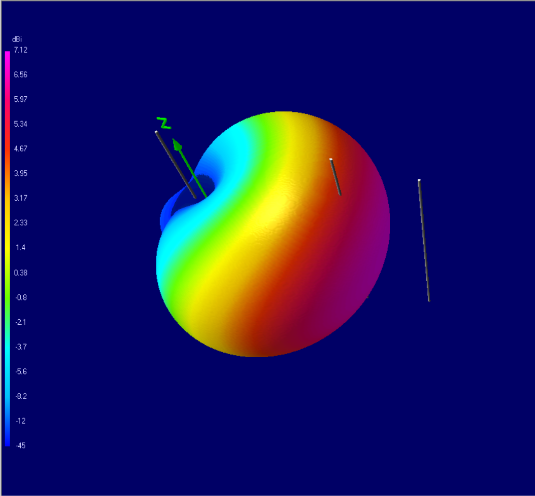
A compact 3-element Yagi designed for hand-held tracking of the ISS on 145.800 MHz. Wide 122° horizontal beamwidth lets you follow a pass without precise aiming - just point roughly toward the ISS and the pattern does the rest. The deep rear null (19.4 dB F/B) rejects ground noise behind you. 8 mm aluminium elements on a ~910 mm boom. Light enough to hold with one hand while operating the radio with the other. Simulated in 4NEC2, free space.
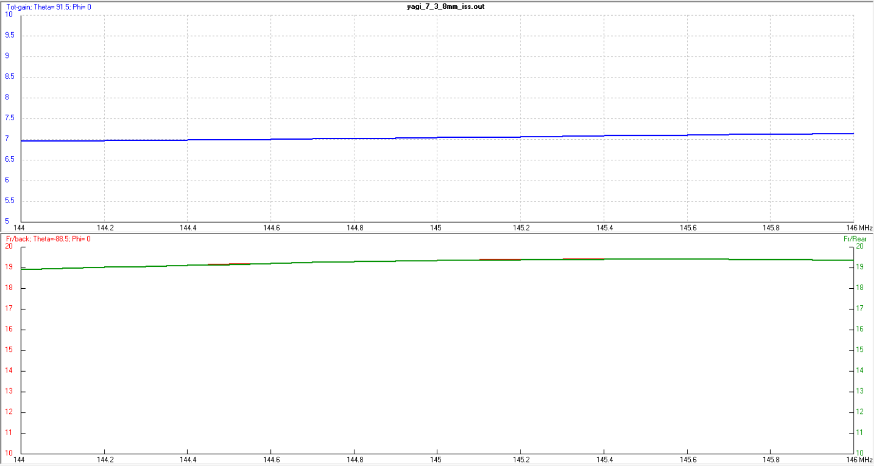
Performance - 145.8 MHz
| Gain | 7.12 dBi |
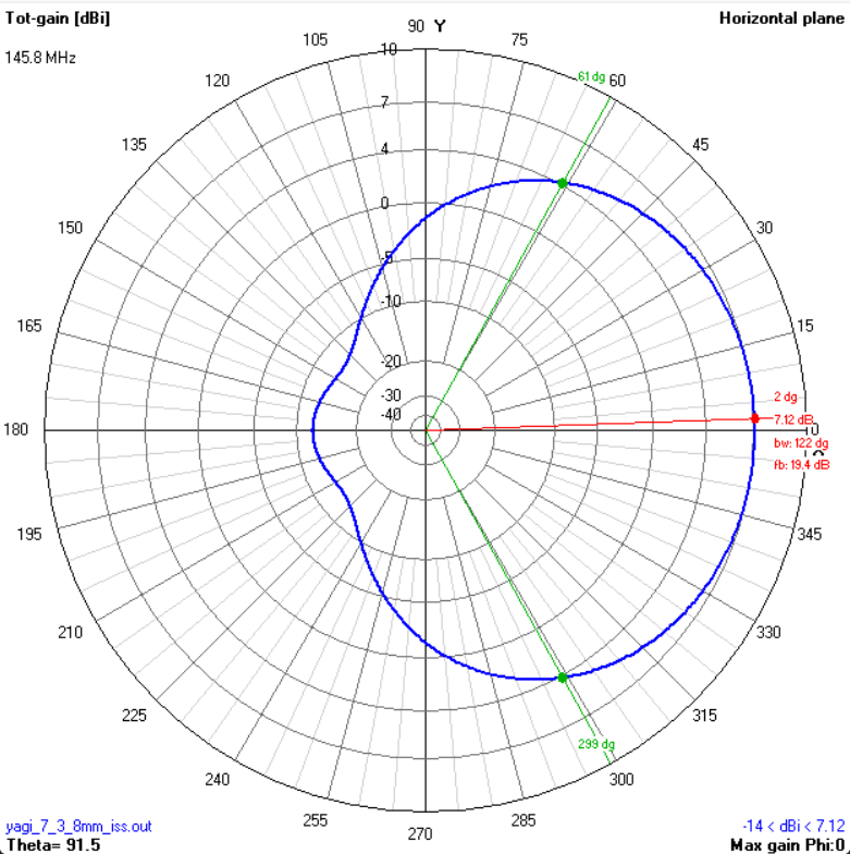
| F/B | 19.4 dB |
| -3 dB E-plane (vertical) | 68° |
| -3 dB H-plane (horizontal) | 122° |
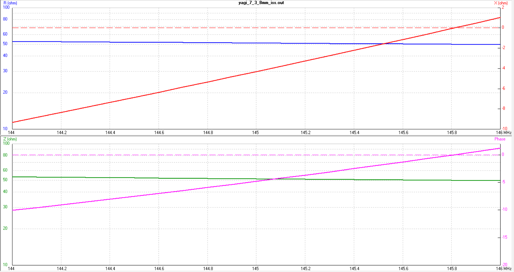
| Impedance at 145 MHz | ~50 + j0 Ω |
| SWR bandwidth (< 1.5:1) | > 144-146 MHz (full band) |
| Polarisation | Horizontal (rotate for ISS passes) |
Geometry
All elements 8 mm Ø aluminium rod, insulated from boom. Positions measured from boom start (reflector at −50 mm). Driven element split at centre with ~5 mm gap for feed.
| Element | Position (mm) | Total length (mm) | Ø (mm) |
|---|---|---|---|
| Reflector | −50 | 1044 | 8 mm |
| Driven element | 559 | 980 | 8 mm |
| Director | 859 | 874 | 8 mm |
Total boom length: ~910 mm (reflector to director). Driven element to reflector: 609 mm. Driven element to director: 300 mm.
Plots

Build Notes
Purpose: This antenna is designed specifically for hand-held ISS tracking - SSTV image reception on 145.800 MHz, APRS on 145.825 MHz, and voice contacts during ISS crew activity. The wide horizontal beamwidth (122°) means you don't need to track the ISS precisely. Point the boom roughly toward the pass and the pattern covers the rest. The deep rear null keeps ground-reflected noise and local interference behind you.
Feed: Direct 50 Ω feed on the driven element. Split at centre with ~5 mm gap. Centre pin to one half, shield to the other. No matching network needed - the impedance sits right at 50 Ω across the band.
Boom: Keep it light. You'll be holding this with one hand for 5-10 minute passes. A fibreglass rod, carbon fibre tube, or thin-wall PVC pipe works well. If using a conductive boom, insulate all elements from the boom - or re-simulate with boom correction.
Handle: A foam grip or PVC T-piece at the balance point (roughly at the driven element) makes tracking comfortable. Some builders attach the coax connector at the handle for a clean cable run.
Polarisation: As the ISS moves across the sky, the polarisation of its signal changes continuously relative to your position on the ground. During a pass, rotate the antenna around the boom axis to find the strongest signal - you'll notice the signal peak and fade as the polarisation shifts. This is normal. Keep adjusting as the ISS travels and you'll maintain a stronger link throughout the pass.
Cable: Keep it short - 2 to 3 metres of RG-58 or RG-316 from the antenna to your handheld or SDR. Every dB counts on satellite reception. A BNC connector is more practical than SO-239 for portable use.
Precision: Element lengths matter. On 2 metres, 5 mm of element length shifts the resonance by about 2-3 MHz. Cut carefully and measure twice.
Materials
| Item | Qty | Specification |
|---|---|---|
| Aluminium tube (8 mm) | ~2.9 m total | 6061-T6 or similar - all three elements |
| Boom | ~910 mm | Lightweight: fibreglass, PVC, or thin-wall aluminium (with isolators!), or just wood |
| Insulated clamps | 3 | Nylon or HDPE, sized for 8 mm rod |
| SMA connector | 1 | 50 Ω - SMA recommended for handheld use, 20-30 centimeters pigtail recommended |
| Coaxial cable | 2-5 m | RG-316 - thin and flexible, easy to wind a few-turn choke at the feed point |