20m Ground Plane - Fishing Rod Vertical
Quarter-wave ground plane for 14 MHz. Household wire on a fibreglass fishing rod. Simulated in 4NEC2 and built with real wire parameters. Works as both portable and permanent installation.
Performance Data
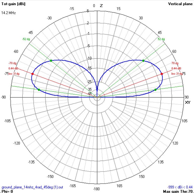
| Gain | 0.5 dBi (over average ground) |
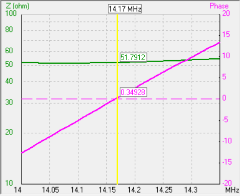
| Impedance | 50 Ω |
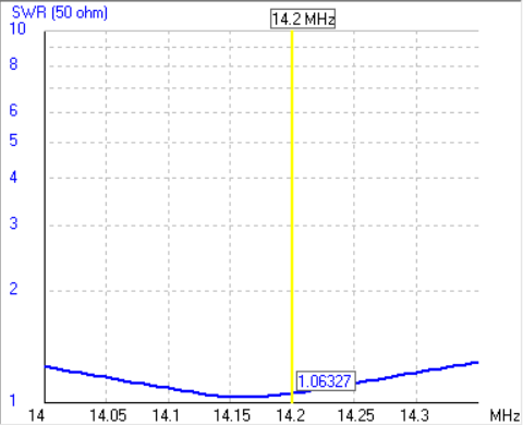
| SWR at 14.000 MHz | 1.25:1 |
| SWR at 14.350 MHz | 1.28:1 |
| Minimum SWR | 1.03:1 |
| Bandwidth (< 1.5:1) | Full 20m band |
| Polarisation | Vertical |
| Power rating | 500 W |
| Feed height | ~4 m |
| Rod length | 7-8 m fibreglass telescopic |
Geometry
| Element | Dimension | Notes |
|---|---|---|
| Vertical radiator | 4.97 m | λ/4 at ~14.15 MHz |
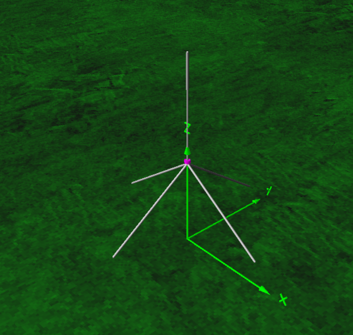
| Radials (×4) | 4.97 m each | 35° droop below horizontal |
| Wire diameter | 1.6 mm | 1.5 mm² household copper (H07V-U) |
| Wire radius (sim) | 0.0008 m |
Simulation Plots

Build Notes
The Fishing Rod
Use a 7-8 m telescopic fibreglass fishing rod. The vertical wire (4.97 m) is cable-tied along the rod with the open end (tip not connected to the connector) at the very top. The feed point sits lower down, roughly 4 m above ground.
CRITICAL: fibreglass only, NEVER carbon fibre. Carbon fibre is conductive - it will couple to the antenna, detune it, and ruin the radiation pattern.
Feed Point
SO-239 on a small ABS box. Vertical wire to centre pin. All four radials to the ground flange. No balun needed - unbalanced antenna on unbalanced coax. No matching network - SWR is already below 1.3:1.
Radials
- Three radials is the absolute minimum. Four is standard.
- Radials must be elevated - that is the whole point. Radials on the ground = different antenna, much higher losses.
- Keep radials straight. Do not fold or bend them - folded radials detune the antenna.
- Roughly 90° apart, roughly same length, roughly 35° droop. Good enough.
Tuning
With the simulated dimensions, the antenna should resonate in the middle of the 20m band without adjustment. Each cm of length change ≈ 15-20 kHz shift. Shorter = higher frequency. Fold the tip back to shorten without cutting.
Materials
| Item | Qty | Specification |
|---|---|---|
| Fibreglass fishing rod | 1 | 7-8 m telescopic, NO carbon fibre |
| Household electrical wire | 25 m | 1.5 mm² single-core copper (H07V-U) |
| SO-239 chassis connector | 1 | Panel mount, 50 Ω |
| Small project box | 1 | ABS or polycarbonate, ~100×60×40 mm |
| Cable ties | 10-15 | UV-resistant, 200 mm |
| Ring terminals / solder lugs | 5 | For connecting radials to SO-239 ground |
| RG-58 coaxial cable | 10-15 m | 50 Ω, with PL-259 connector |
| Ground stake or tripod | 1 | To support the fishing rod base |
| Self-amalgamating tape | 1 roll | For weatherproofing the feed point |