20m / 15m / 10m Multiband Stacked Fan Dipole
Three dipoles sharing a single feed point - 14, 21, and 28 MHz. The 20m dipole is horizontal, the 15m droops at 15°, and the 10m at 25° (inverted-V). 2 mm wire, 6 m feed height. Simulated in 4NEC2 over real ground. Not the best performance or results, but for limited space or portable operation, it can be an option.
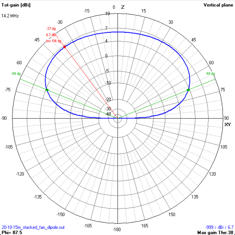
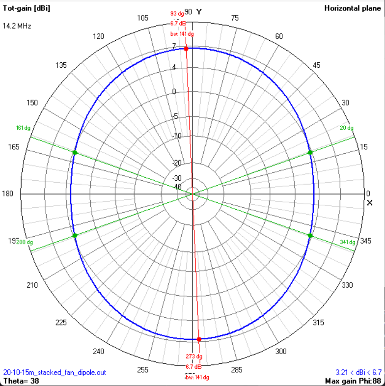
Performance - 20m (14 MHz)
| Gain | ~7.5 dBi (broadside) |
| -3 dB E-plane (vertical) | ~50° |
| -3 dB H-plane (horizontal) | Omnidirectional (dipole) |
| Impedance at 14 MHz | ~72 + j0 Ω |
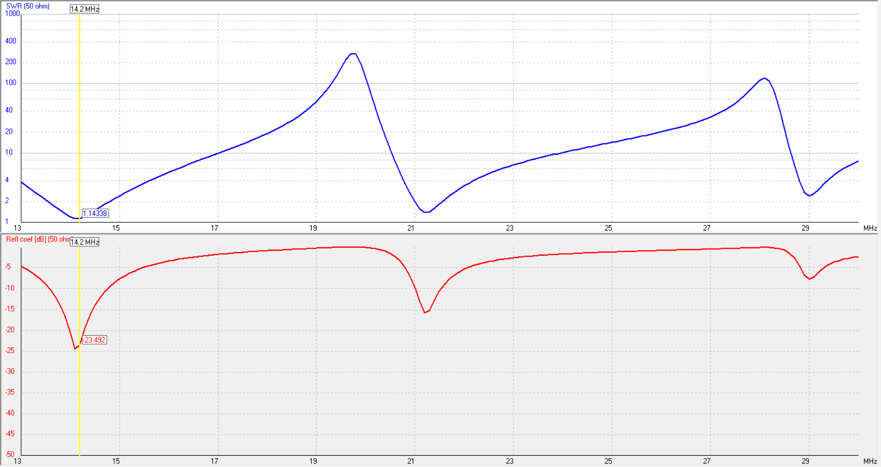
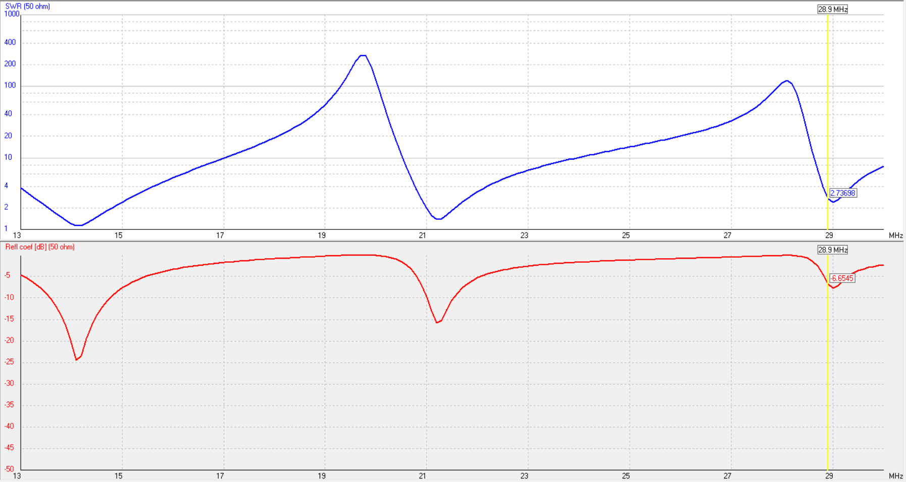
| SWR min | ~1.4:1 @ 14 MHz |
| SWR bandwidth (< 2:1) | ~13.8-14.4 MHz |
| Polarisation | Horizontal |
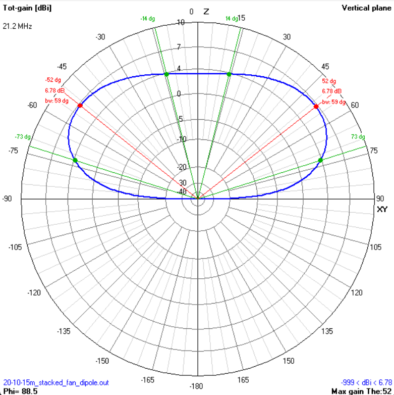
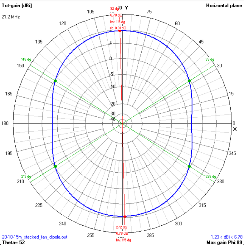
Performance - 15m (21 MHz)
| Gain | ~7.0 dBi (broadside) |
| -3 dB E-plane (vertical) | ~55° |
| -3 dB H-plane (horizontal) | Omnidirectional (dipole) |
| Impedance at 21 MHz | ~65 + j0 Ω |
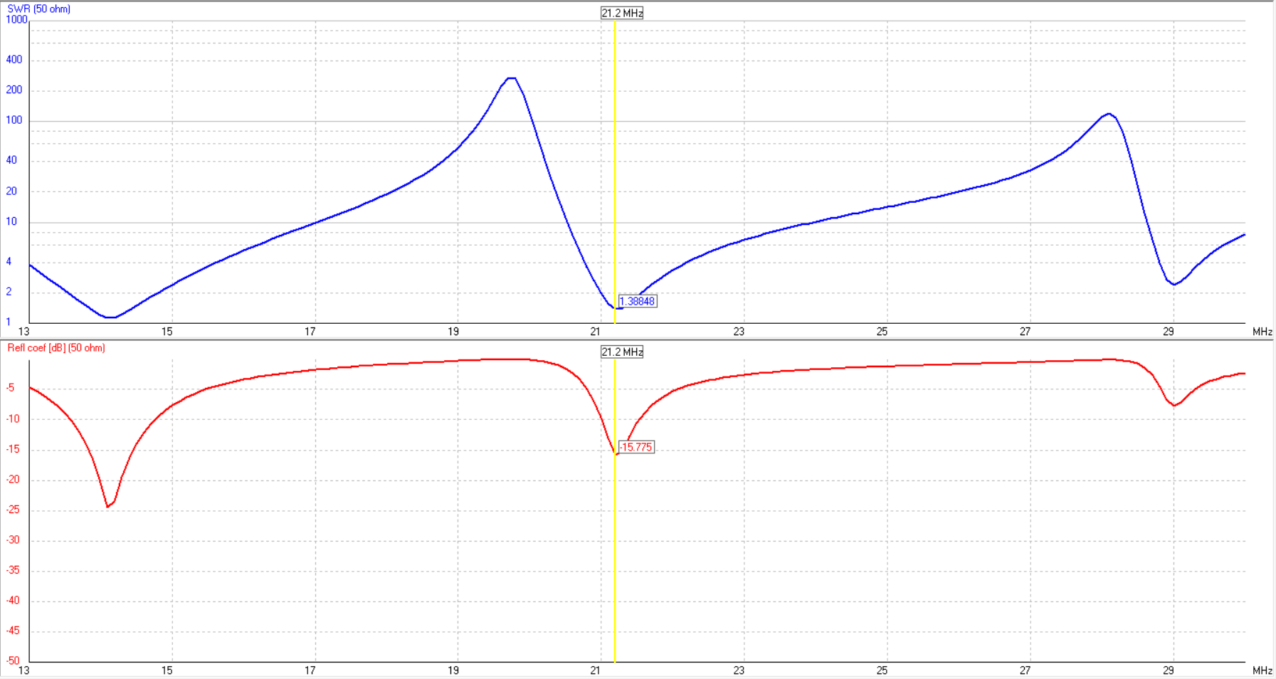
| SWR min | ~1.3:1 @ 21 MHz |
| SWR bandwidth (< 2:1) | ~20.8-21.5 MHz |
| Polarisation | Horizontal |
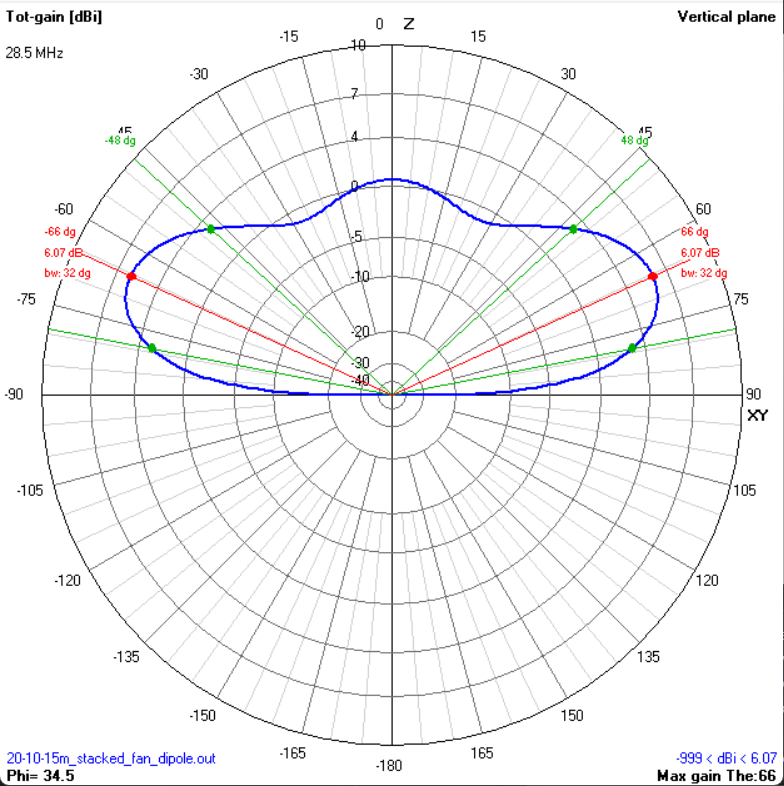
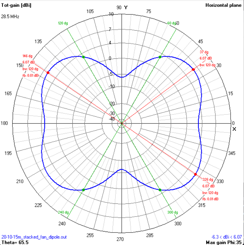
Performance - 10m (28 MHz)
| Gain | ~6.5 dBi (broadside) |
| -3 dB E-plane (vertical) | ~60° |
| -3 dB H-plane (horizontal) | Omnidirectional (dipole) |
| Impedance at 28 MHz | ~60 + j0 Ω |
| SWR min | ~1.2:1 @ 28 MHz |
| SWR bandwidth (< 2:1) | ~27.5-29.0 MHz |
| Polarisation | Horizontal |
Geometry
All three dipoles connect at a common centre point (feed segment ±100 mm). The 20m pair runs horizontal. The 15m and 10m pairs droop progressively to separate them physically and reduce interaction.
| Element | Span (mm) | Length (mm) | Ø | Band | Orientation |
|---|---|---|---|---|---|
| 20m Dipole (left) | −5000 to −100 | 4900 | 2 mm | 14 MHz | Horizontal |
| Feed segment | −100 to +100 | 200 | 2 mm | All | Horizontal |
| 20m Dipole (right) | +100 to +5000 | 4900 | 2 mm | 14 MHz | Horizontal |
| 15m Dipole (left) | −100 to −3476 | 3600 | 2 mm | 21 MHz | 15° droop |
| 15m Dipole (right) | +100 to +3476 | 3600 | 2 mm | 21 MHz | 15° droop |
| 10m Dipole (left) | −100 to −2491 | 2750 | 2 mm | 28 MHz | 25° droop |
| 10m Dipole (right) | +100 to +2491 | 2750 | 2 mm | 28 MHz | 25° droop |
Total span: ~10 m tip-to-tip (20m dipole). Feed height: 6 m. The 15m tips hang at ~5.07 m, the 10m tips at ~4.84 m.
Plots - 20m (14 MHz)
Plots - 15m (21 MHz)
Plots - 10m (28 MHz)
Build Notes
Feed: Single feed point at the centre. All six dipole legs connect at the same junction - centre pin to one side of each pair, shield to the other. Direct 50 Ω feed. The natural impedance is around 60-72 Ω depending on band, so expect SWR in the 1.2-1.5:1 range without matching.
Balun: A 1:1 current balun (RF choke) at the feed point is essential. Without it, common-mode currents on the coax shield will distort the pattern and bring RF into the shack. Use a good ferrite choke rated for the power you intend to run.
Droop angles: The 15° and 25° droop angles separate the dipole pairs physically and reduce mutual coupling. They also lower the impedance slightly on the drooped bands. If you change the droop angles, re-simulate - the interaction between the three pairs shifts the resonances.
Tuning: Tune the 20m dipole first (it's the longest and least affected by the others). Then tune 15m, then 10m. Each adjustment may shift the others slightly - iterate until all three bands are where you want them. Trim from the tips.
Wire: 2 mm copper or aluminium wire. Stranded wire is easier to work with for a field antenna. Solid wire holds its shape better for a permanent installation.
Support: The feed point needs to be at 6 m or higher. A single mast, tree branch, or fibreglass pole works. The wire ends can slope down to lower supports or tie off to trees/stakes.
Materials
| Item | Qty | Specification |
|---|---|---|
| Copper or aluminium wire (2 mm) | ~24 m total | Three dipole pairs + feed segment |
| Centre insulator / junction plate | 1 | Connects all 6 dipole legs + feed |
| Rope / halyard | ~15 m | Dacron or UV-resistant nylon for support |
| Mast or tree support | 1 | 6 m minimum height at feed point |
| SO-239 or N-type connector | 1 | Panel mount, 50 Ω |
| Coaxial cable | 10-20 m | RG-213 recommended (50 Ω) |
| RF choke (1:1 current balun) | 1 | Ferrite choke at feed point - essential |
| End insulators | 6 | Egg or dog-bone insulators for wire ends |