20m Ground Plane — Fishing Rod Vertical
A quarter-wave ground plane vertical for the 20-metre band built from household electrical wire and a fibreglass fishing rod. Simulated and built with real wire parameters. SWR 1.25:1 at 14 MHz, 1.28:1 at 14.35 MHz. Works as both a portable and permanent installation.
Design & Principle
20m Ground Plane Vertical — Fishing Rod Build
Why This Antenna
The quarter-wave ground plane is one of the simplest and most effective vertical antennas you can build. It needs no tuner, no balun, no matching network, and no complicated feed system. For the 20-metre band, it's about 5 metres tall — which fits perfectly on a cheap fibreglass fishing rod from any sporting goods store.
The entire antenna can be built from hardware store materials in under an hour. Total cost: under 30 EUR.
Already Simulated — Real Wire Parameters
This design has been fully simulated in 4NEC2 and built using the actual parameters of 1.5mm² household electrical wire (1.6mm conductor diameter, copper conductivity). The simulation uses a feed height of 4 metres, four radials at 35° droop, and average ground conditions.
The results speak for themselves:
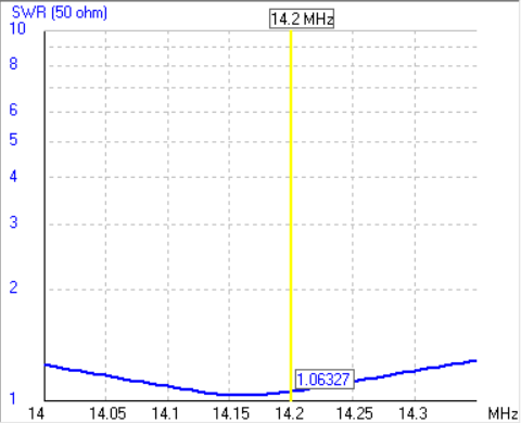
- SWR at 14.000 MHz: 1.25:1
- SWR at 14.350 MHz: 1.28:1
- Minimum SWR: 1.03:1
- Entire 20m band covered below 1.3:1 SWR
That's with plain household wire — no special antenna wire, no expensive materials. The simulation file is available for download below so you can verify and experiment yourself in 4NEC2.
The Design
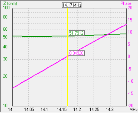
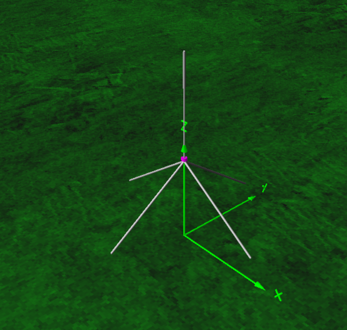
A quarter-wave vertical works by radiating against a ground plane of radial wires. The vertical element is approximately λ/4 long (4.97m for ~14.15 MHz), and four radials of the same length provide the counterpoise. The radials droop downward at about 35°, which brings the feed impedance close to 50 Ω — giving an excellent match to 50 Ω coax.
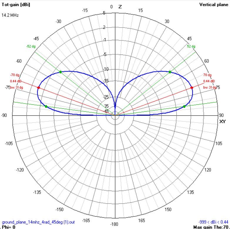
The radiation pattern is omnidirectional in azimuth with a low takeoff angle — ideal for DX on 20 metres. Check the radiation pattern plots above to see the elevation and 3D patterns from the simulation.
The Fishing Rod: 7-8 Metres, Fibreglass Only
Use a 7-8 metre telescopic fibreglass fishing rod as the support mast. The vertical wire (4.97m) is cable-tied along the rod with the open end (the tip not connected to the connector) at the very top of the rod. The feed point and connector sit lower down, roughly 4 metres above ground depending on the rod length and base mount.
With the rod mounted on a base (ground stake, tripod, or a simple bracket), the feed point sits at roughly 4 metres above ground. This gives the radials enough clearance to droop naturally without touching the ground near the base.
CRITICAL: use FIBREGLASS, not carbon fibre. Carbon fibre is electrically conductive. A carbon rod will couple to the antenna element, detune it, absorb RF energy, and completely ruin the radiation pattern. Your SWR will be unpredictable, your efficiency will drop, and you'll wonder why the antenna doesn't work.
Fibreglass is an excellent RF insulator — transparent to radio waves. The wire taped to a fibreglass rod behaves exactly as if it were suspended in free air.
How to tell the difference: fibreglass rods are usually translucent or light-coloured (white, cream, pale green). Carbon fibre rods are black or dark grey and feel stiffer for their weight. If in doubt, check the label or ask the shop. Many cheap telescopic rods (under 20 EUR) are fibreglass — the expensive ones tend to be carbon.
Why Household Electrical Wire
Standard 1.5mm² single-core household wire (H07V-U or equivalent) is perfect for this antenna:
- It's copper, which has excellent conductivity
- It's stiff enough to hold its shape along the rod
- It's insulated, so it won't short against anything
- It's available everywhere for about 0.30 EUR/metre
- The 1.6mm conductor diameter gives good bandwidth on 20m
The simulation was run with exactly this wire diameter (0.0008m radius) and copper conductivity. The SWR numbers above are what you'll get in practice (within normal construction tolerances).
You can also use stranded wire (H07V-K) — it's more flexible and easier to coil for transport, but doesn't hold its shape as well on the rod. For a portable setup that gets packed often, stranded is more practical. For a semi-permanent installation, solid core is neater.
Feed Point Construction
The feed point is where the vertical element meets the radials and the coax. Keep it simple:
- Mount an SO-239 connector on a small ABS project box
- Solder the vertical wire to the centre pin
- Solder all four radials to the ground flange — use ring terminals for easy assembly/disassembly if you want a portable setup
- The coax plugs into the SO-239 from below
No balun needed — this is an unbalanced antenna fed with unbalanced coax. No matching network needed — the SWR is already below 1.3:1 across the entire band.
Radial Tips
- Three radials is the absolute minimum. Four is the standard and what this design uses. More radials (six or eight) will lower ground loss slightly, but four already works very well.
- The radials must be elevated — that's the whole point of this antenna. Radials lying on the ground turn it into a completely different antenna with much higher losses. Keep them in the air, drooping from the feed point.
- Keep the radials as straight as possible. Don't fold or bend them to fit a small space — folded radials will detune the antenna and degrade performance. If you don't have room for full-length straight radials, this isn't the right antenna for that location.
- The radials don't need to be perfectly spaced. "Roughly 90° apart, roughly the same length, roughly drooping at 35°" is good enough.
Tuning
With the simulated dimensions (4.97m vertical, 4.97m radials, 35° droop, 4m feed height), the antenna should resonate right in the middle of the 20m band without any adjustment. But real-world conditions (nearby objects, ground conductivity, exact wire length) can shift things slightly.
If you need to tune:
- Each centimetre of length change moves the resonance by about 15-20 kHz
- Shorter wire = higher resonant frequency
- Longer wire = lower resonant frequency
- Fold the tip back on itself to shorten without cutting
Simulation Files
The 4NEC2 simulation file is available for download. Open it in 4NEC2 to see the full SWR sweep, radiation patterns, impedance plot, and current distribution. All the SY variables are editable — change the wire length, droop angle, feed height, or number of segments and re-run to see the effect.
Performance
Don't let the simplicity fool you. A quarter-wave ground plane on 20 metres, even built from household wire and a fishing rod, is a serious DX antenna. The low takeoff angle of a vertical is ideal for long-distance contacts, and 20 metres is the workhorse DX band.
With 100 watts and this antenna, you'll work stations across continents. It won't beat a 3-element Yagi at 20m height — nothing this simple will. But it'll outperform a dipole at low height (under 10m), because the vertical's low-angle radiation gets out where a low dipole's high-angle pattern doesn't.
And it costs 30 EUR instead of 300.
Quick Specs
| Parameter | Value |
|---|---|
| Frequency Range | 14.0 - 14.35 MHz |
| Gain | 0.5 dBi (over average ground) |
| Impedance | 50 Ω |
| Polarization | Vertical |
| Installation Type | Portable |
| Space Required | Small garden |
| Multiband | No |
Performance Plots
SWR Plot
Radiation Pattern (E/H Plane)

Impedance (Z & Phase)
Other
Materials
| Item | Quantity | Specification |
|---|---|---|
| Fibreglass fishing rod | 1 | 7-8m telescopic, NO carbon fibre |
| Household electrical wire | 25m | 1.5mm² single-core copper (H07V-U or similar) |
| SO-239 chassis connector | 1 | Panel mount, 50 Ω |
| Small project box | 1 | ABS or polycarbonate, ~100x60x40mm |
| Cable ties | 10-15 | UV-resistant, 200mm |
| Ring terminals or solder lugs | 5 | For connecting radials to SO-239 ground |
| RG-58 coaxial cable | 10-15m | 50 Ω, with PL-259 connector |
| Ground stake or tripod | 1 | To support the fishing rod base |
| Self-amalgamating tape | 1 roll | For weatherproofing the feed point |
Construction Steps
- 1
Cut the vertical radiator: measure and cut 4.97m of 1.5mm² household wire. This is the quarter-wave element for ~14.15 MHz. Leave 5cm extra at the bottom for connection to the SO-239 centre pin.
- 2
Cut four radials: cut four pieces of the same wire, each 4.97m long. Leave 5cm extra on each for connection.
- 3
Prepare the feed point box: mount the SO-239 connector on the project box. Solder the vertical radiator wire to the centre pin. Solder all four radial wires to the ground flange using ring terminals or direct solder — space them evenly around the connector.
- 4
Attach the vertical wire to the fishing rod: extend the fibreglass rod fully (7-8m) and cable-tie the radiator wire along its length, starting from the base. The wire runs from the feed point box up to about 4.97m height. The extra rod length above the wire provides structural support.
- 5
Mount the rod: use a ground stake, tripod, or rod holder to support the fishing rod base. With a 7-8m rod and a base mount, the feed point sits at roughly 4m above ground. The overall antenna height depends on the rod length plus the base height.
- 6
Deploy the radials: spread the four radial wires outward from the feed point, roughly 90° apart. Let them droop naturally at about 30-45° below horizontal. They can rest on the ground, on bushes, or be tied to short stakes.
- 7
Connect the coax: attach the PL-259 end of your RG-58 cable to the SO-239 on the feed point box. Run the cable to your transceiver.
- 8
Tune: check SWR with a NanoVNA or SWR meter. The resonant point should be near 14.15 MHz. If too high, add a few cm of wire. If too low, fold the tip back. Aim for SWR below 1.5:1.
- 9
Weatherproof: wrap the feed point connections with self-amalgamating tape. If using outdoors permanently, seal the project box with silicone.
Measurements & Tuning
Downloads
20m Ground Plane — Fishing Rod Vertical — Build Sheet
Quick Specs
| Parameter | Value |
|---|---|
| Frequency Range | 14.0 - 14.35 MHz |
| Gain | 0.5 dBi (over average ground) |
| Impedance | 50 Ω |
| Polarization | Vertical |
| Installation Type | Portable |
| Space Required | Small garden |
| Multiband | No |
Materials
| Item | Quantity | Specification |
|---|---|---|
| Fibreglass fishing rod | 1 | 7-8m telescopic, NO carbon fibre |
| Household electrical wire | 25m | 1.5mm² single-core copper (H07V-U or similar) |
| SO-239 chassis connector | 1 | Panel mount, 50 Ω |
| Small project box | 1 | ABS or polycarbonate, ~100x60x40mm |
| Cable ties | 10-15 | UV-resistant, 200mm |
| Ring terminals or solder lugs | 5 | For connecting radials to SO-239 ground |
| RG-58 coaxial cable | 10-15m | 50 Ω, with PL-259 connector |
| Ground stake or tripod | 1 | To support the fishing rod base |
| Self-amalgamating tape | 1 roll | For weatherproofing the feed point |
Construction Steps
- 1
Cut the vertical radiator: measure and cut 4.97m of 1.5mm² household wire. This is the quarter-wave element for ~14.15 MHz. Leave 5cm extra at the bottom for connection to the SO-239 centre pin.
- 2
Cut four radials: cut four pieces of the same wire, each 4.97m long. Leave 5cm extra on each for connection.
- 3
Prepare the feed point box: mount the SO-239 connector on the project box. Solder the vertical radiator wire to the centre pin. Solder all four radial wires to the ground flange using ring terminals or direct solder — space them evenly around the connector.
- 4
Attach the vertical wire to the fishing rod: extend the fibreglass rod fully (7-8m) and cable-tie the radiator wire along its length, starting from the base. The wire runs from the feed point box up to about 4.97m height. The extra rod length above the wire provides structural support.
- 5
Mount the rod: use a ground stake, tripod, or rod holder to support the fishing rod base. With a 7-8m rod and a base mount, the feed point sits at roughly 4m above ground. The overall antenna height depends on the rod length plus the base height.
- 6
Deploy the radials: spread the four radial wires outward from the feed point, roughly 90° apart. Let them droop naturally at about 30-45° below horizontal. They can rest on the ground, on bushes, or be tied to short stakes.
- 7
Connect the coax: attach the PL-259 end of your RG-58 cable to the SO-239 on the feed point box. Run the cable to your transceiver.
- 8
Tune: check SWR with a NanoVNA or SWR meter. The resonant point should be near 14.15 MHz. If too high, add a few cm of wire. If too low, fold the tip back. Aim for SWR below 1.5:1.
- 9
Weatherproof: wrap the feed point connections with self-amalgamating tape. If using outdoors permanently, seal the project box with silicone.
Measurements
verticalLength: 4.97m (quarter-wave at ~14.15 MHz)
radialLength: 4.97m each
numberOfRadials: 4
radialDroopAngle: 35° below horizontal
feedHeight: ~4m (rod base + mount height)
rodLength: 7-8m fibreglass telescopic
wireDiameter: 1.6mm (1.5mm²)
minimumSWR: 1.03:1
swrAt14MHz: 1.25:1
swrAt14350MHz: 1.28:1
bandwidth: Full 20m band below 1.5:1 SWR
powerRating: 500W